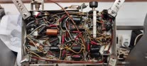
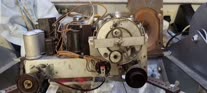
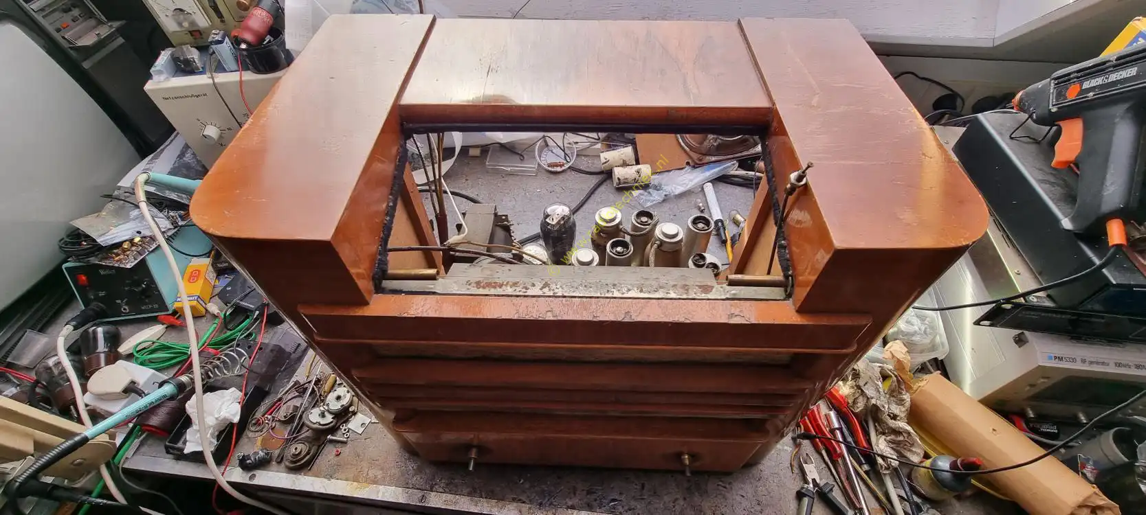
The story of the Philips 695A Rondo. It all started with this demolition chassis. Sometimes you need some parts.
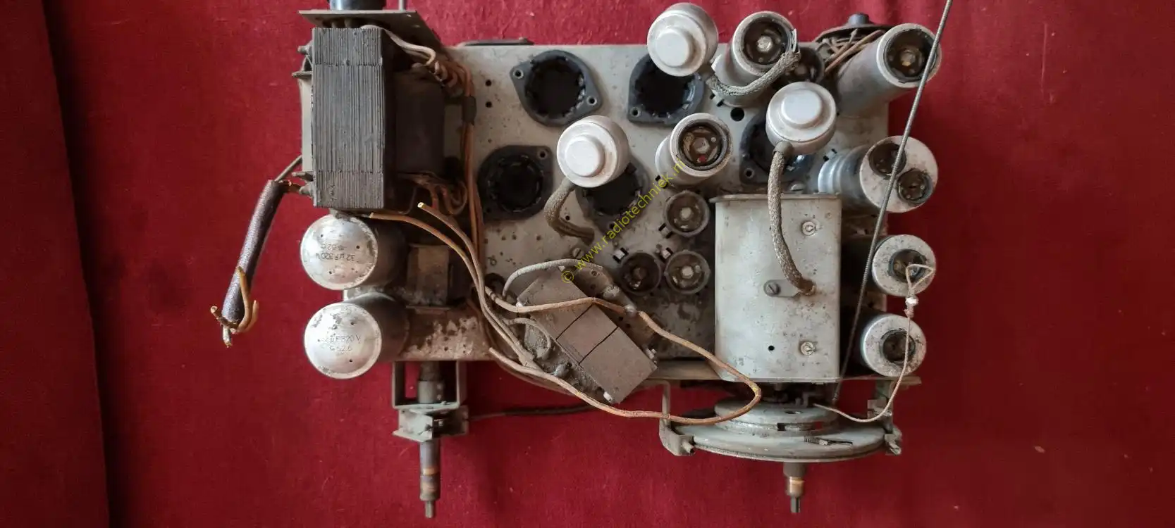
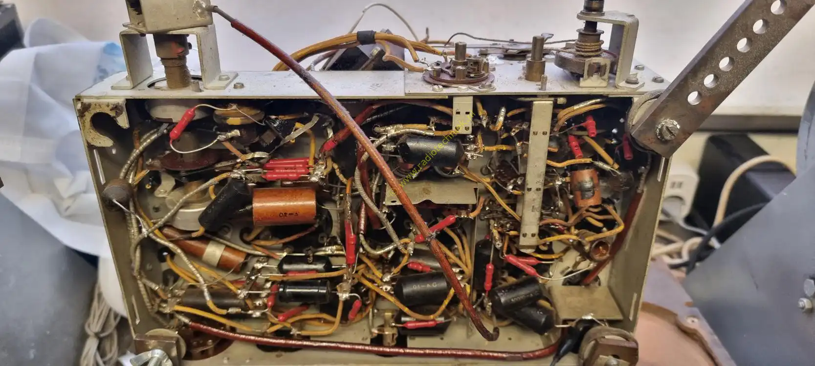
And if we look at this chassis, it is quite a nice chassis.
In retrospect, I didn't need the parts after all. So chassis back into the corner until that.....

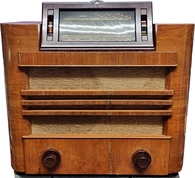
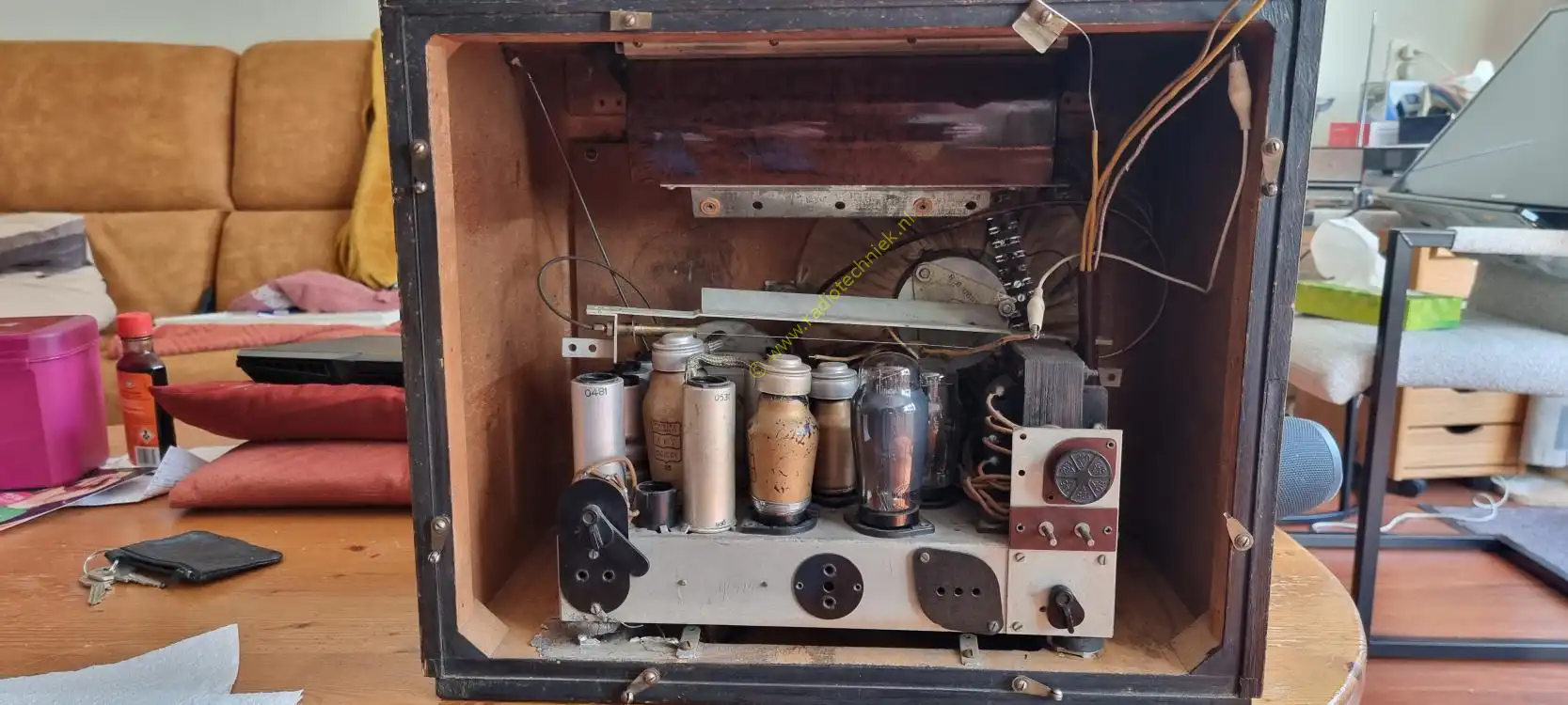
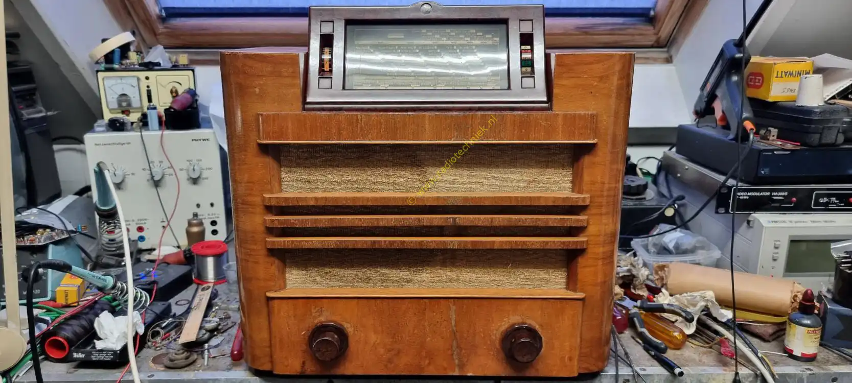
Someone had found a case of a Philips Rondo 695A.
The chassis in the cabinet was missing the output transformer. The wiring was completely cut to pieces. The speaker and dial cover were missing.
So it is time for a Philips 695A restoration.
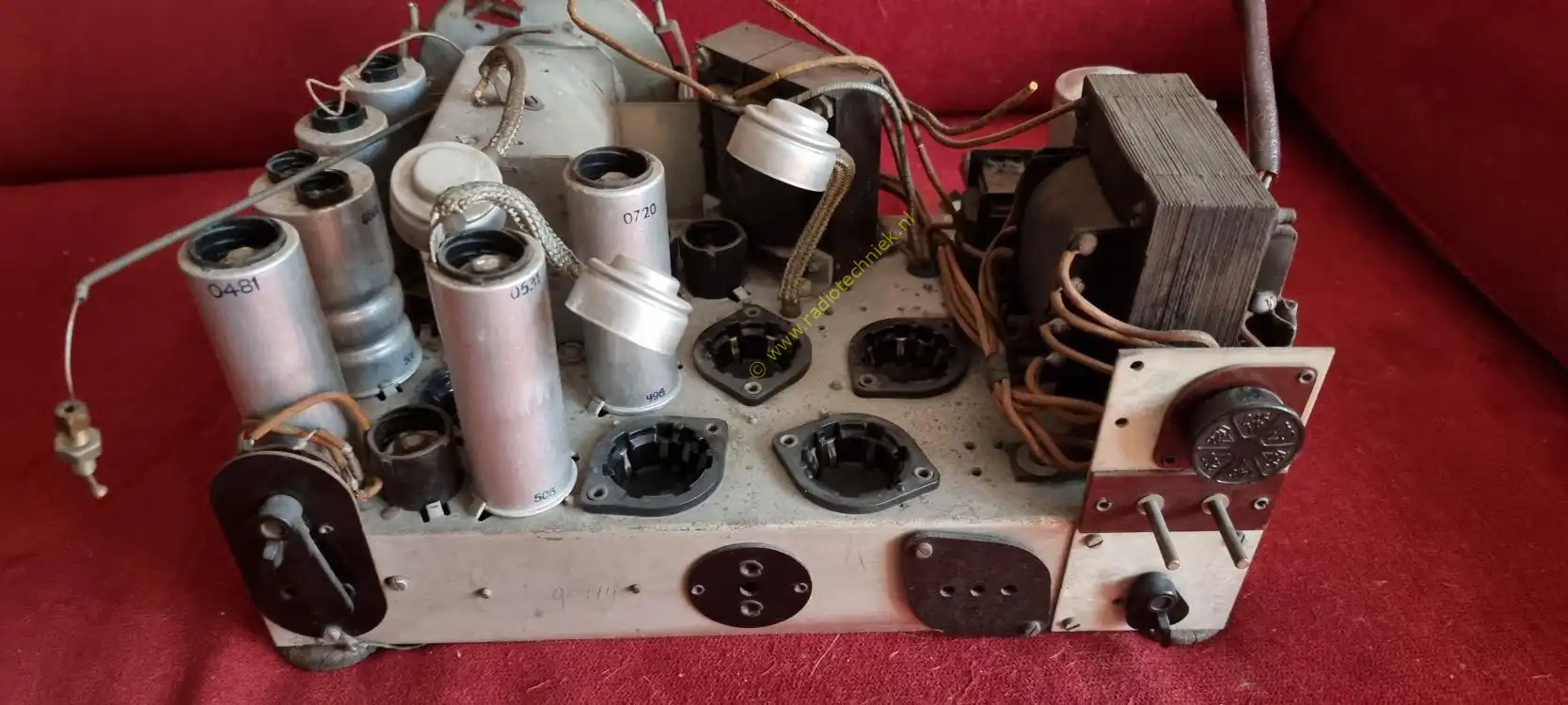
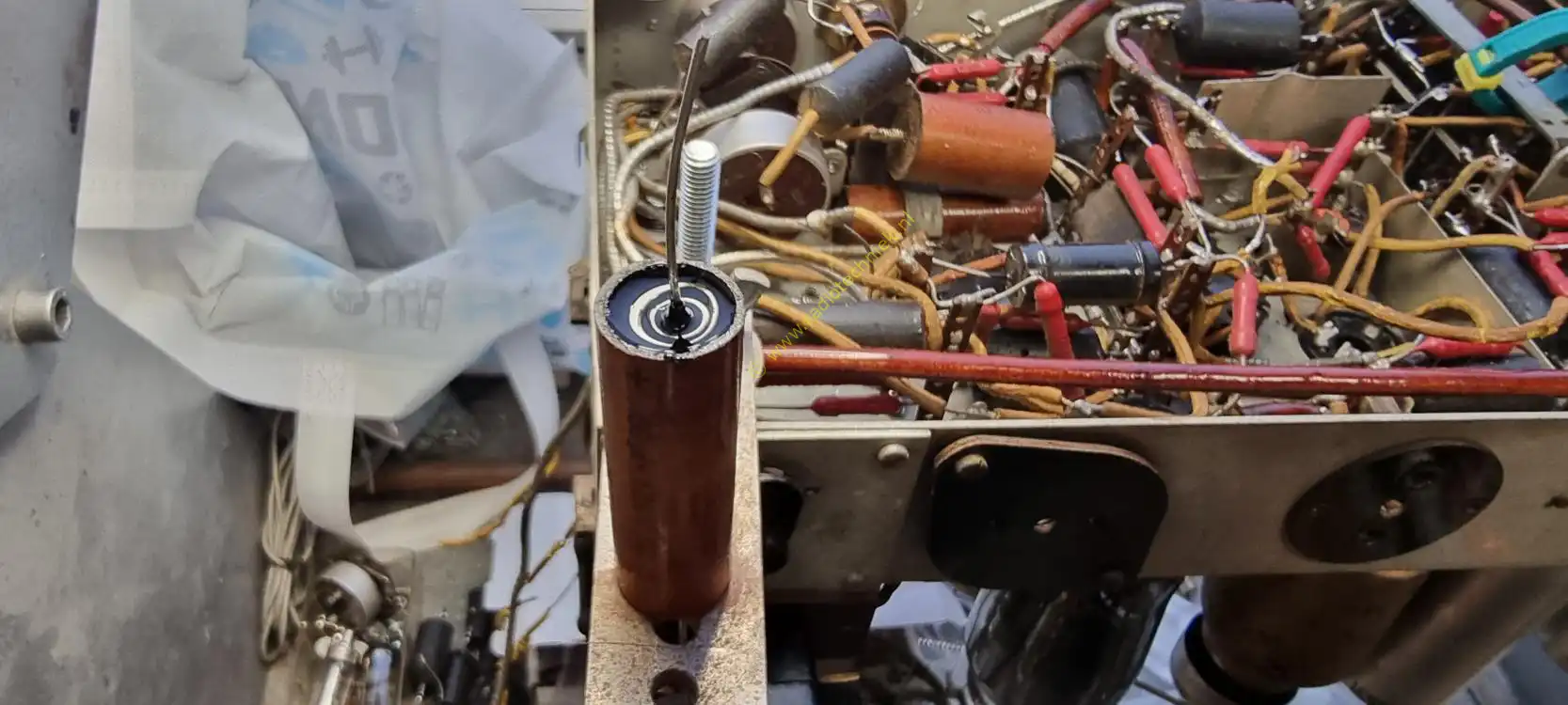
The electrolytic capacitors were already leaking a bit and I was just in time to restore these capacitors. Otherwise the chassis would have suffered permanent damage.
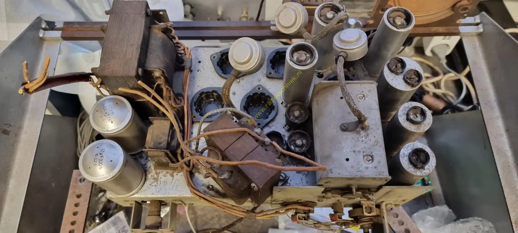
Both electrolytic capacitors restored and placed back on the chassis. Then it's time to test.
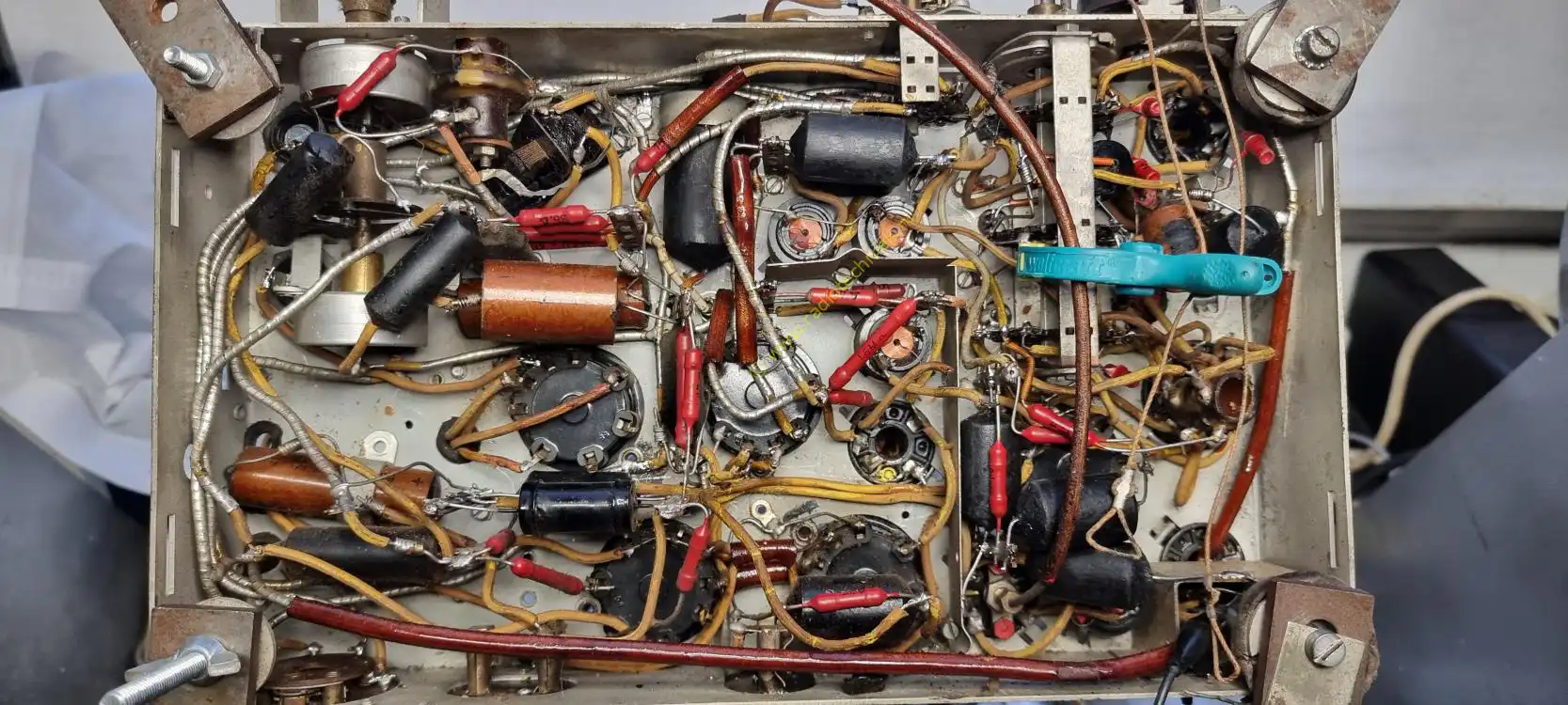
And it turns out that the chassis is playing. All capacitors are so leaky that the only thing you can do is replace everything. The wave range switch is so bad that you can hear cracking and grinding in the sound. And time will tell whether that can be achieved.
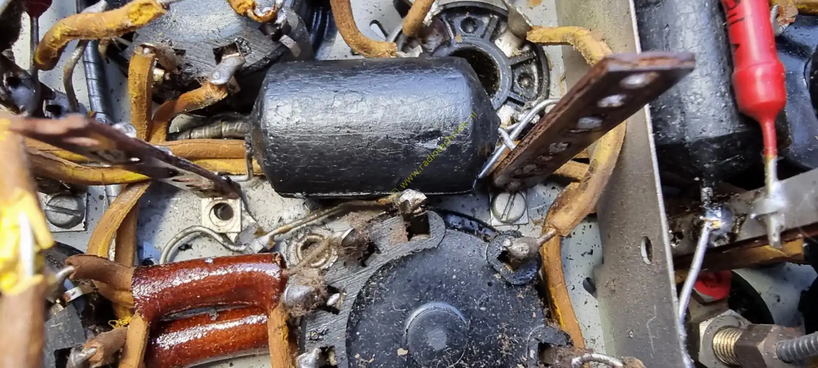
We start by disassembling the wave range switch. We will immediately replace the defective tar capacitors. We only use original parts.
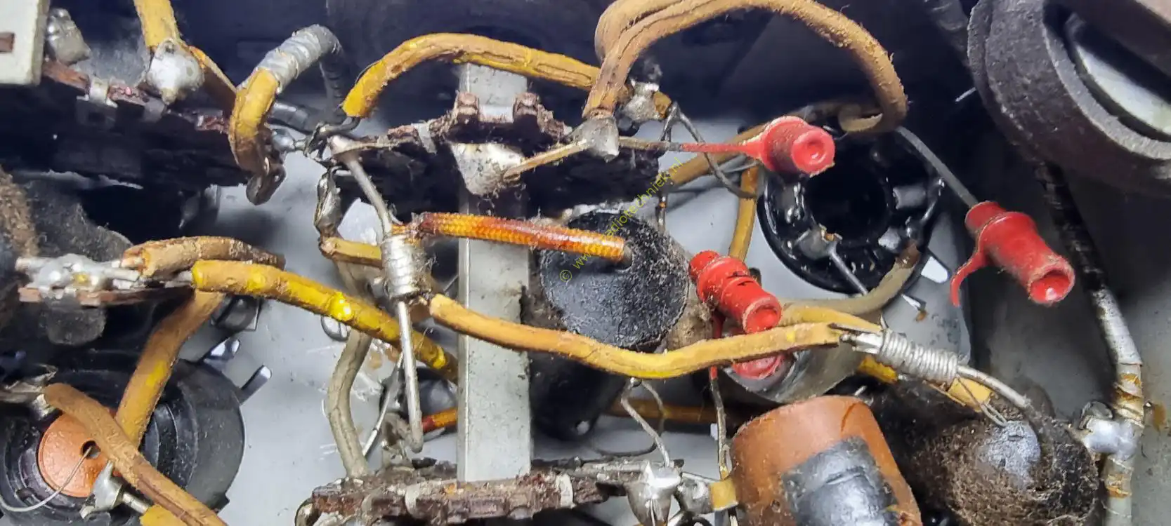
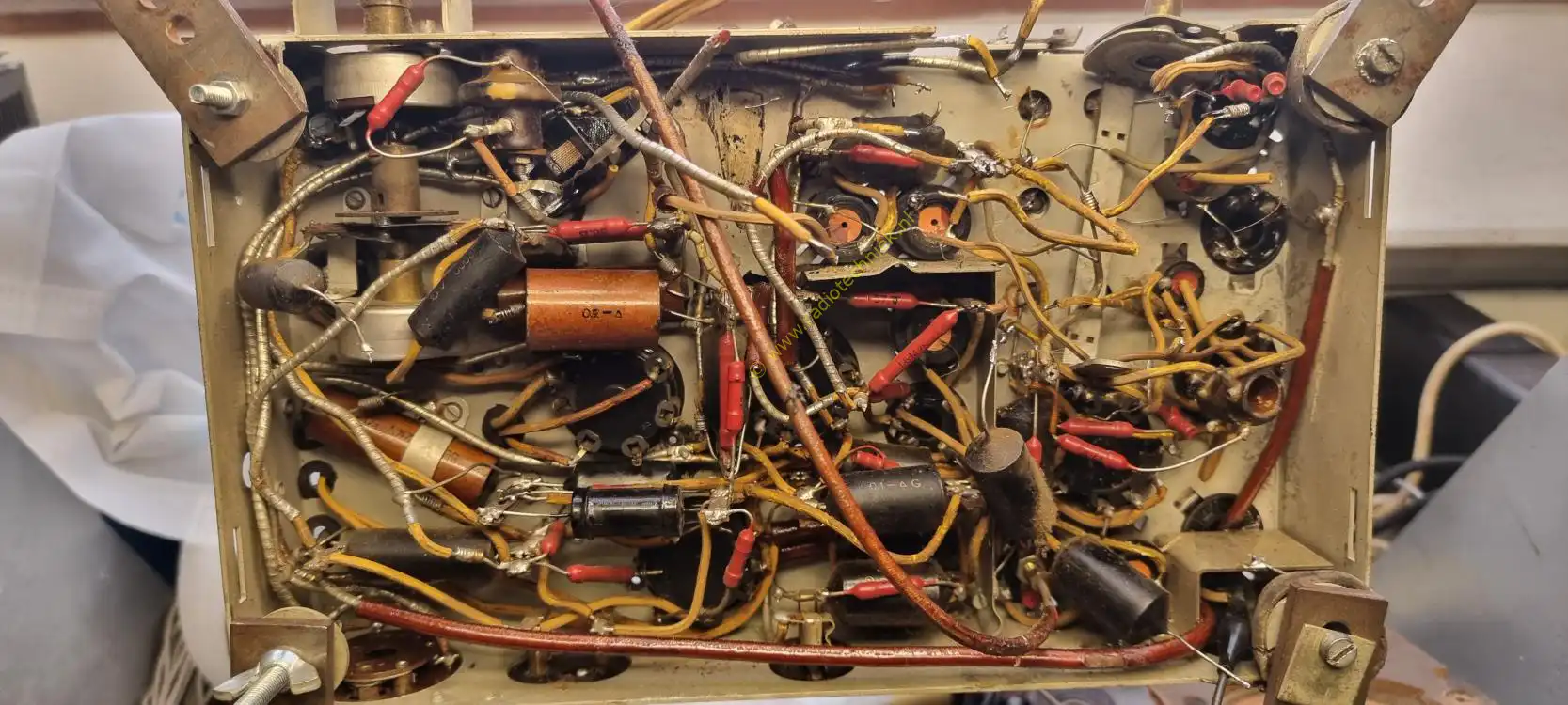
We take detailed photos so that we know how things are assembled. This was once put together in the factory. The ash scrapes through the tar capacitor.
Just a complete overview of the wave range switch.
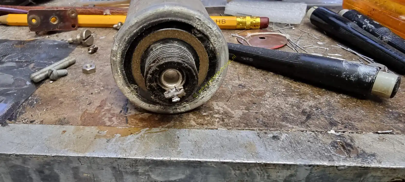
The shaft of the wave range switch can be slid out of the switches at the bottom.
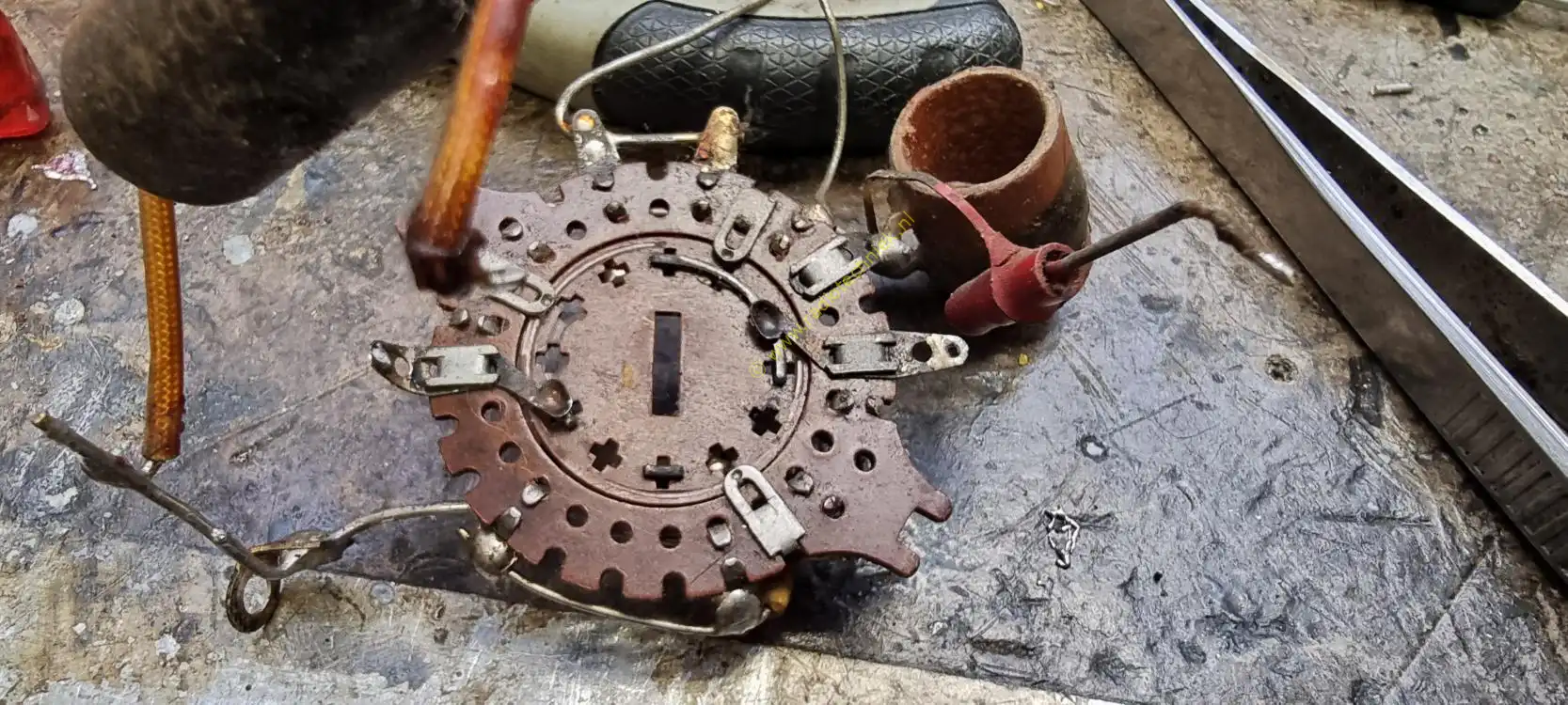
This is a switch deck of the wave range switch. This was a new model in 1936 and also the worst link deck they made.
Here I am removing the last deck of the wave range switch. It is a major job, but it is certainly doable.
When all the switching covers are removed from the wave range switch, it looks like this.
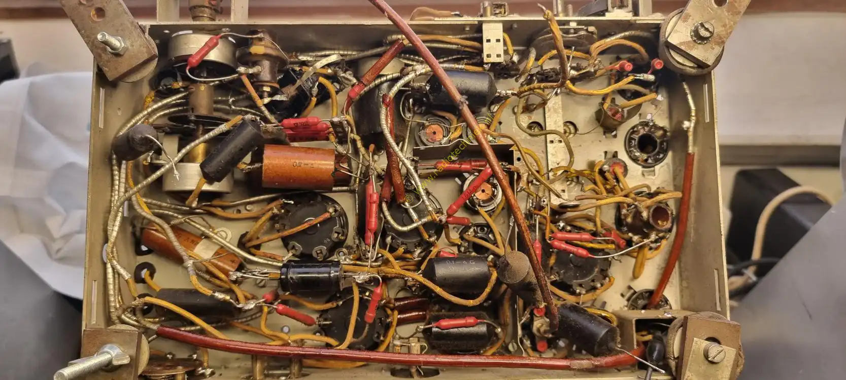
Here you can clearly see that once the plate that holds the wave range switches is removed, you get a lot of space to disassemble things.
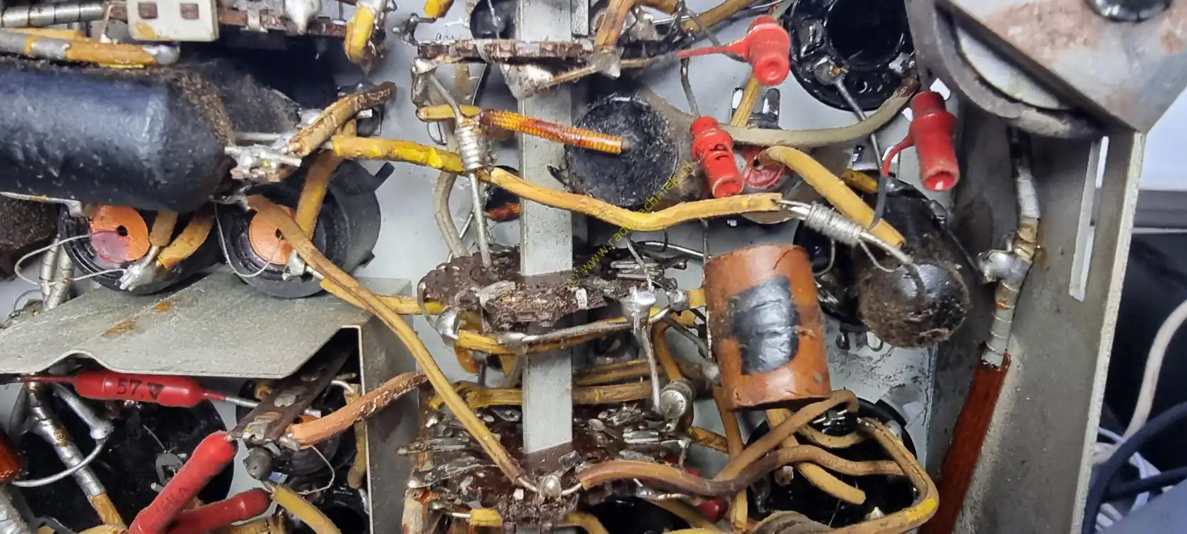
At the top center you can now easily reach a huge tar capacitor. Here it has now been removed.
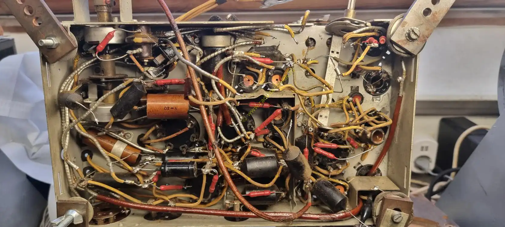
This is where the reconstruction started. The order in which the wave range switch is replaced is very important.
It is best to place the middle deck of the wave range switch last.
And when everything is put back it will look something like this. Then a question immediately arises. Could the chassis still play?
And wow, it's unbelievable, but it still works. As if it were the most normal thing in the world.
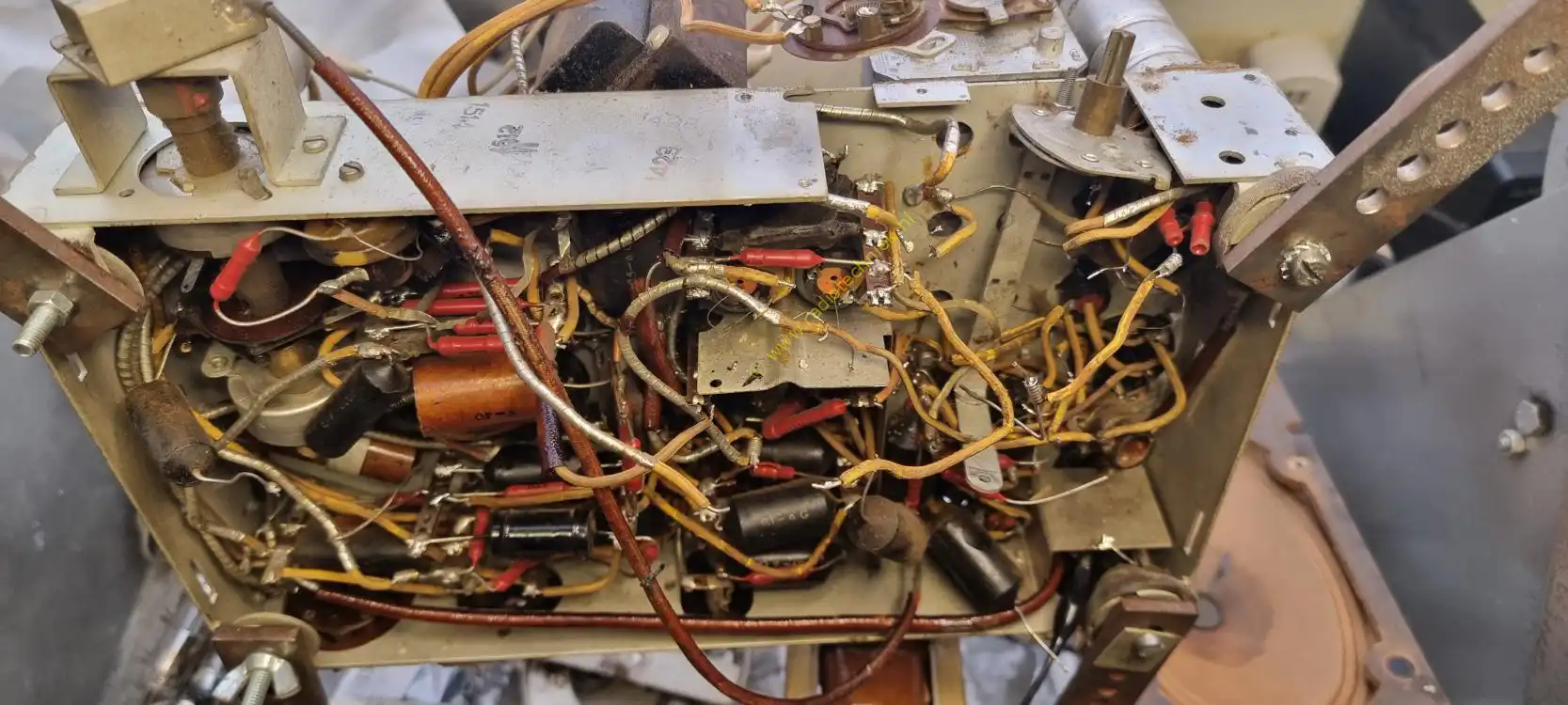
And then things go wrong. This tar capacitor was so stuck that it was impossible to get it out. A shielded wire runs underneath this tar capacitor. Because it is cut in half at the top, this wire must be replaced. This wasn't actually possible but I had no choice.
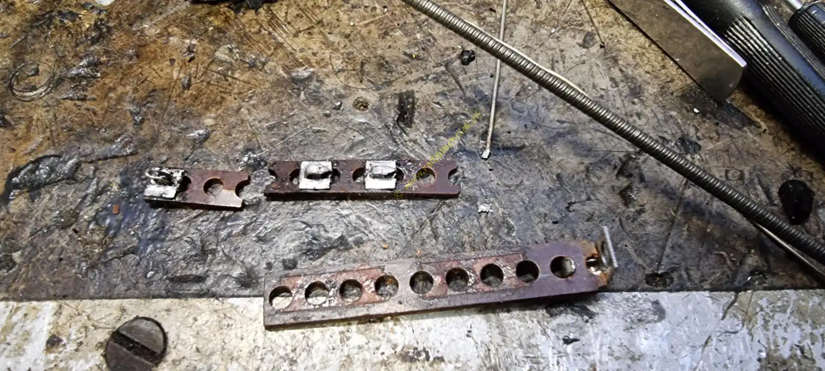
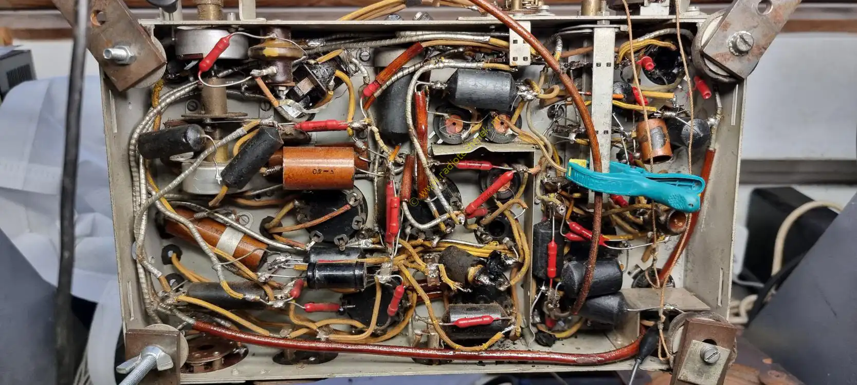
Broken resistance support. So a new one had to be made.
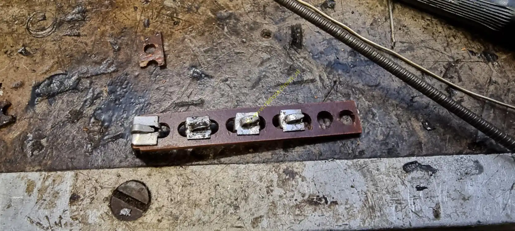
And this is what the resistance support looks like.
Here the shielded wire has been removed.
The cathode electrolytic capacitor of the power tube had to be removed. So just replace it with a new electrolytic capacitor.
The electrolytic capacitor and the new shielded wire have been reinstalled.
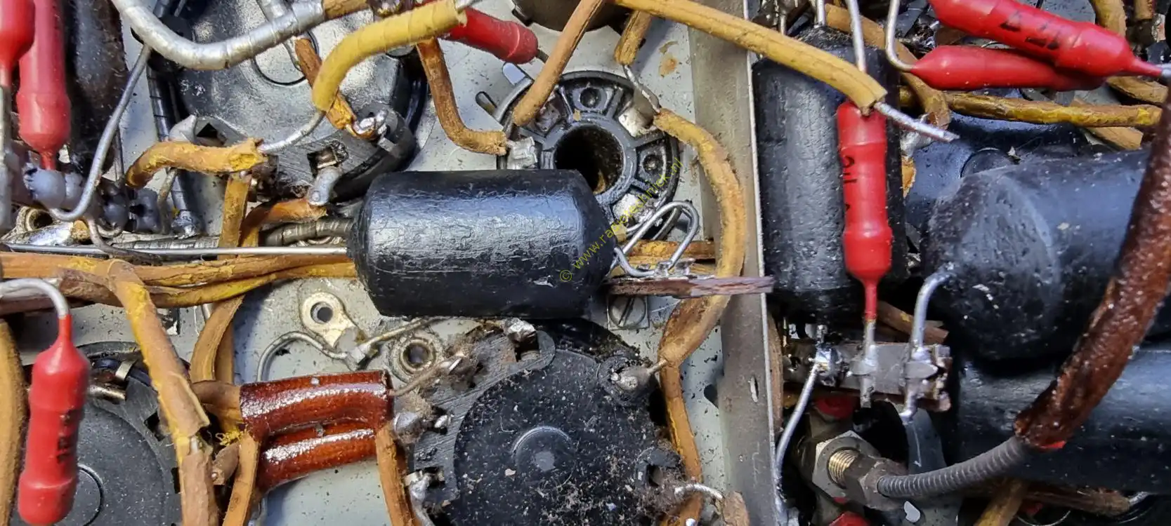
And now replace the tar capacitor that was so stuck. It's quite a precision job, but it's going well.
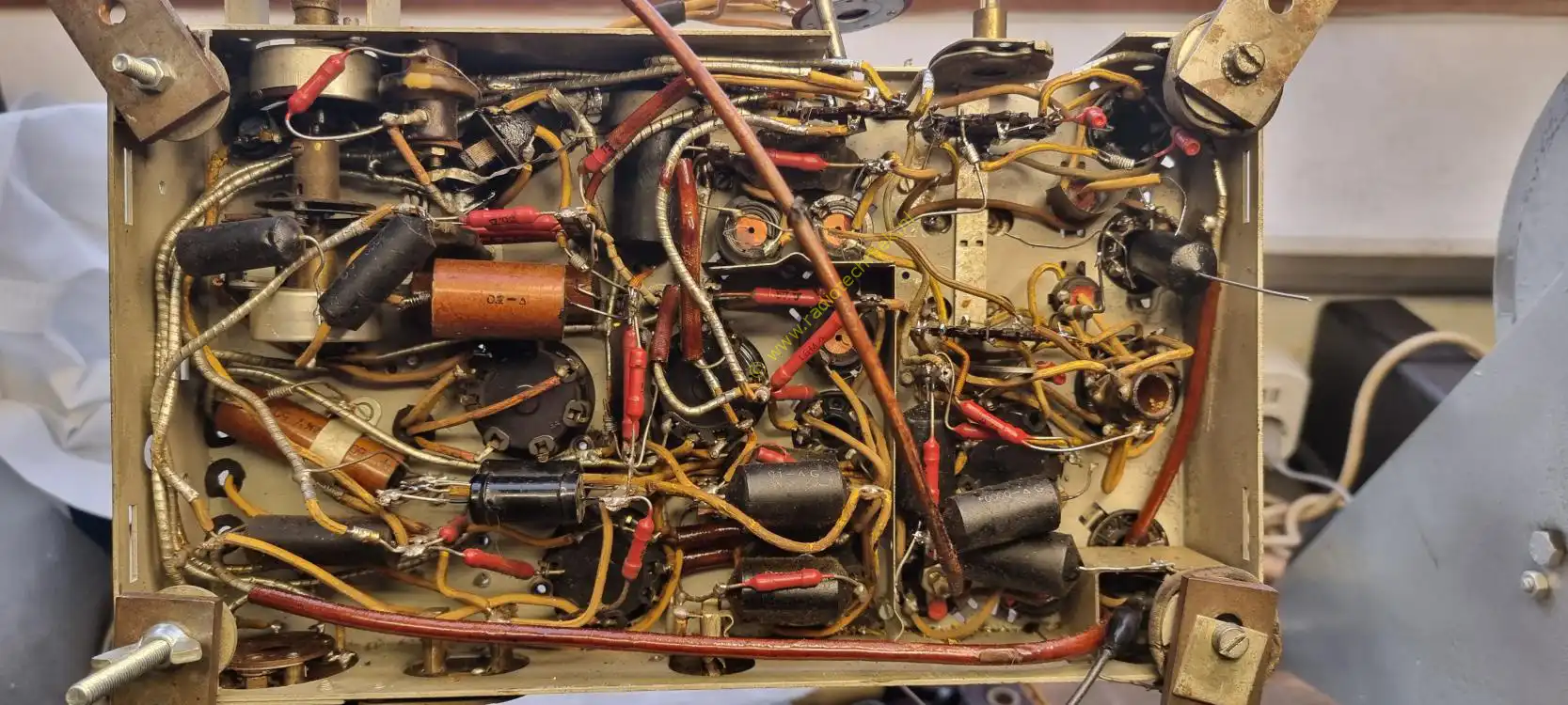
It's going to be something like that.
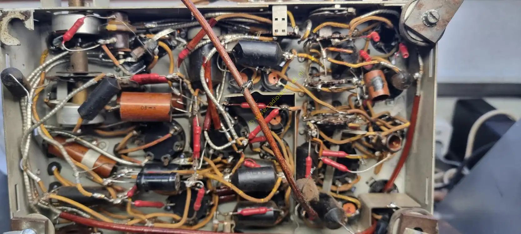
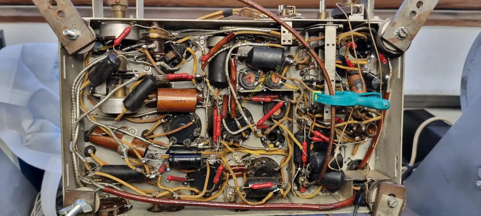
And then when everything is reassembled it looks like this. A test didn't seem to go well.
Everything seems to work but the sound at full volume is quite soft.
The tuning wheel and drive cord have now also been installed.
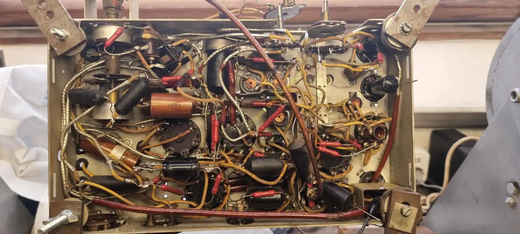
Just an overview of the whole at the top.
There was a 1.6 mega ohm resistor at the very bottom of the chassis and it was open.
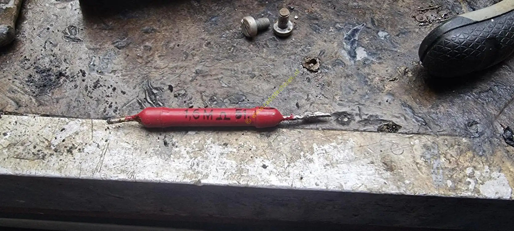
And this is the resistor it was in series with the grid of the preamp tube.
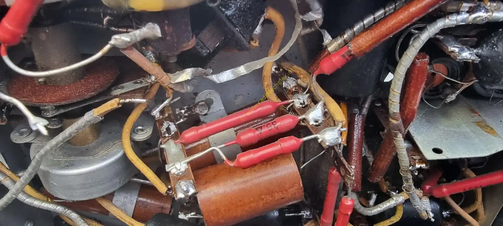
To get an idea of what a hassle it is to replace a simple resistor.
After replacing the resistor, everything works properly.
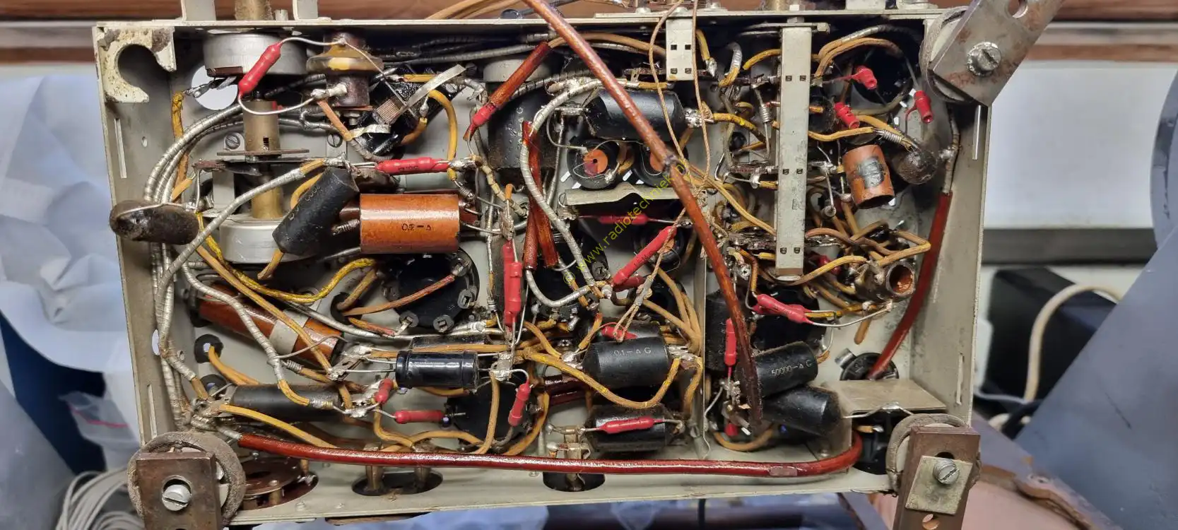
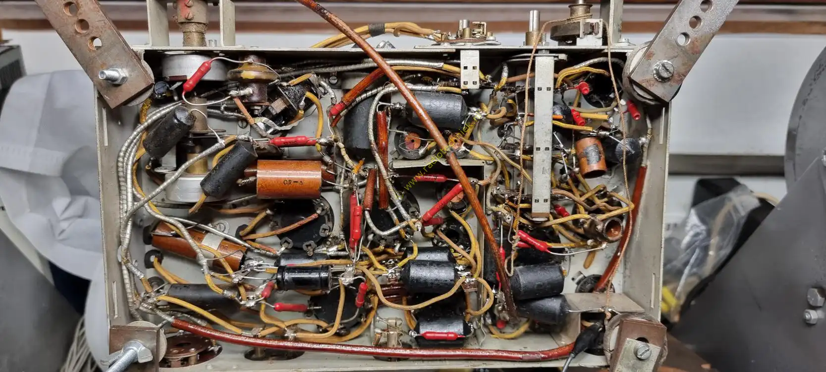
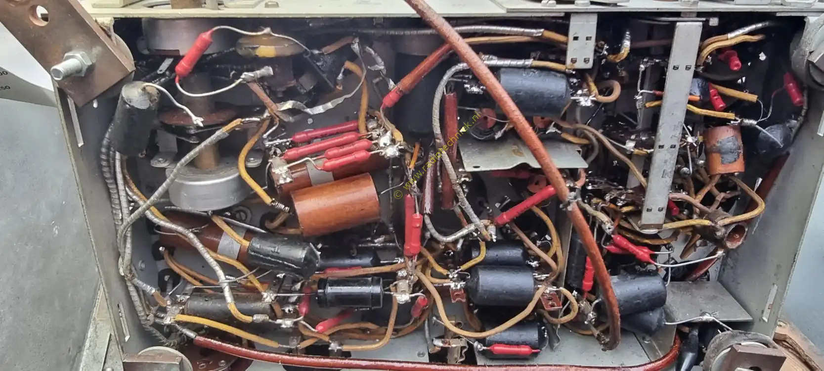
The bottom view. The chassis already seems like a lot, but it also needs to be adjusted.

A test of the tuning indicator.
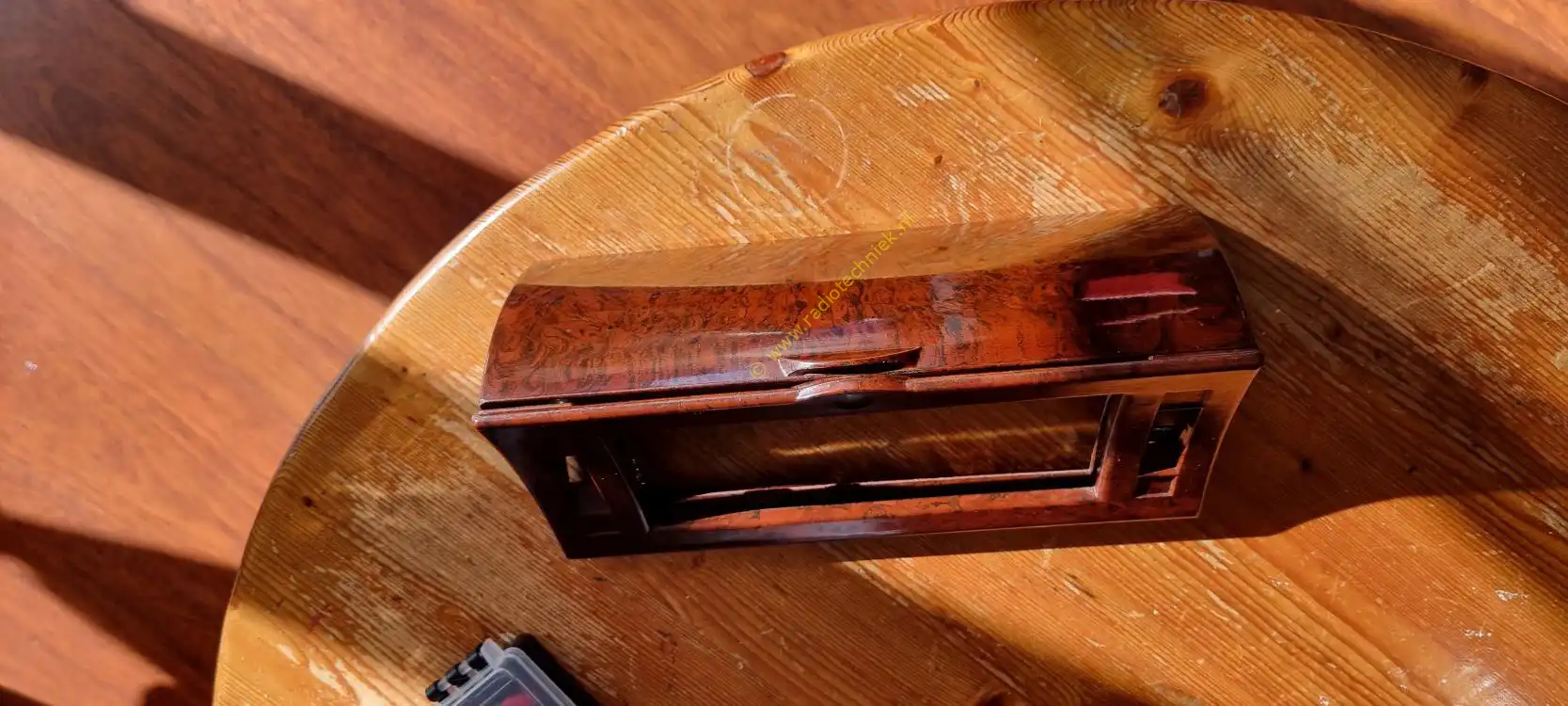
The dial cover that came with the chassis also needs to be restored.

Needs no further explanation.
The wiring in the dial cover.
The dial cover after cleaning and polishing.
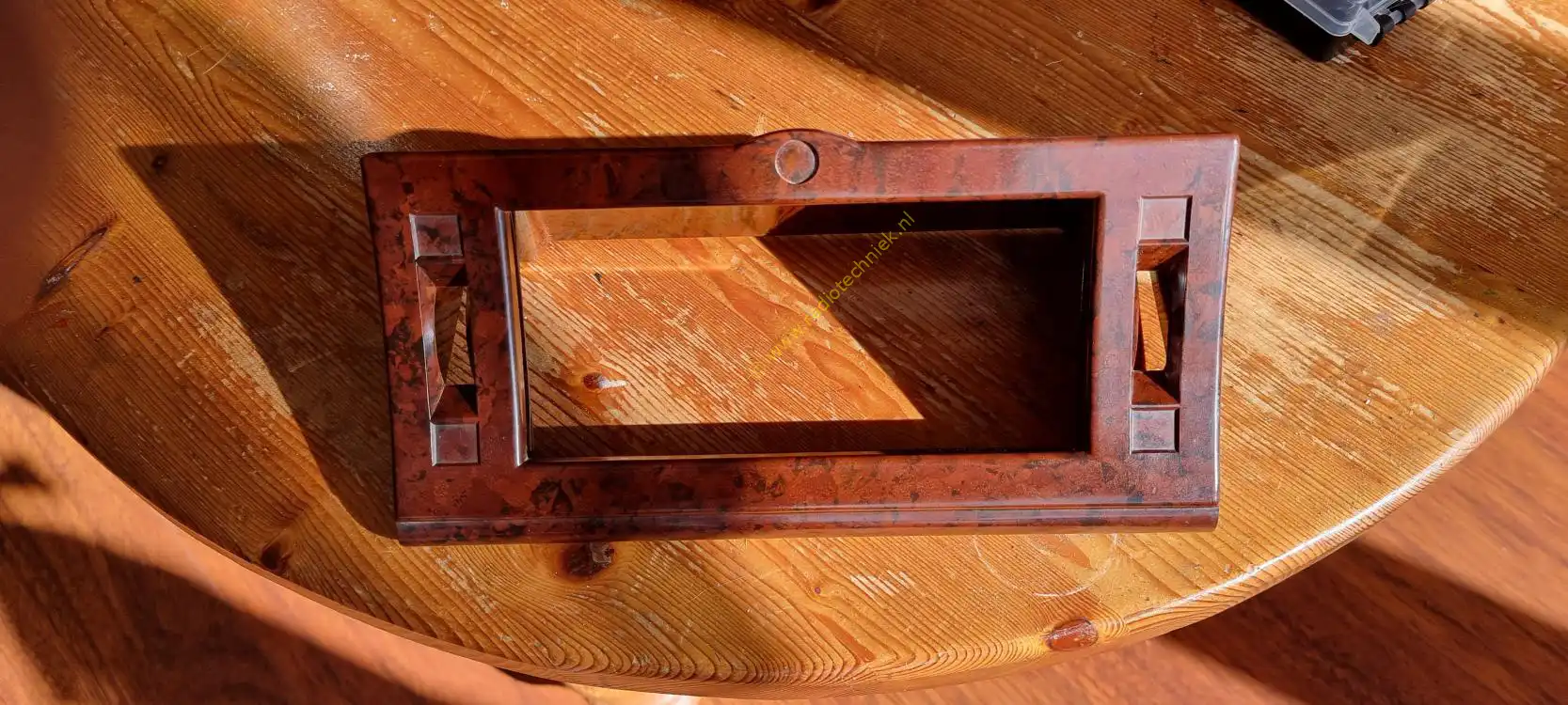
The front view of the dial cover.
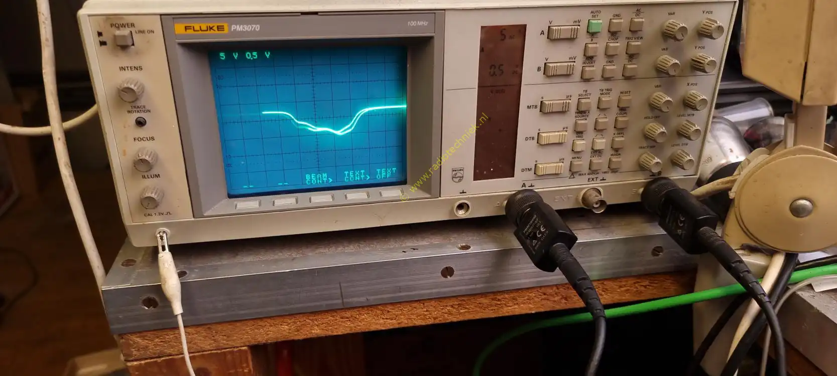
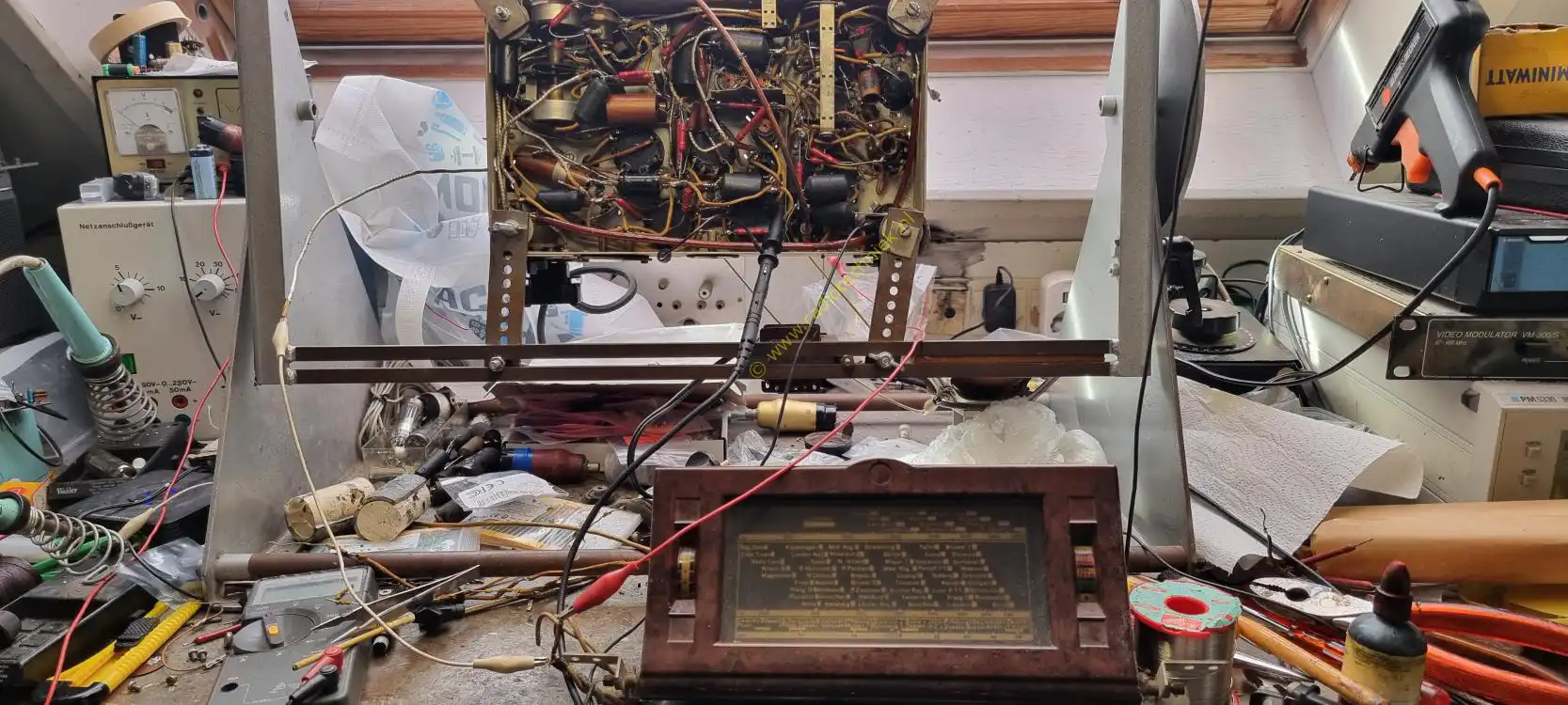
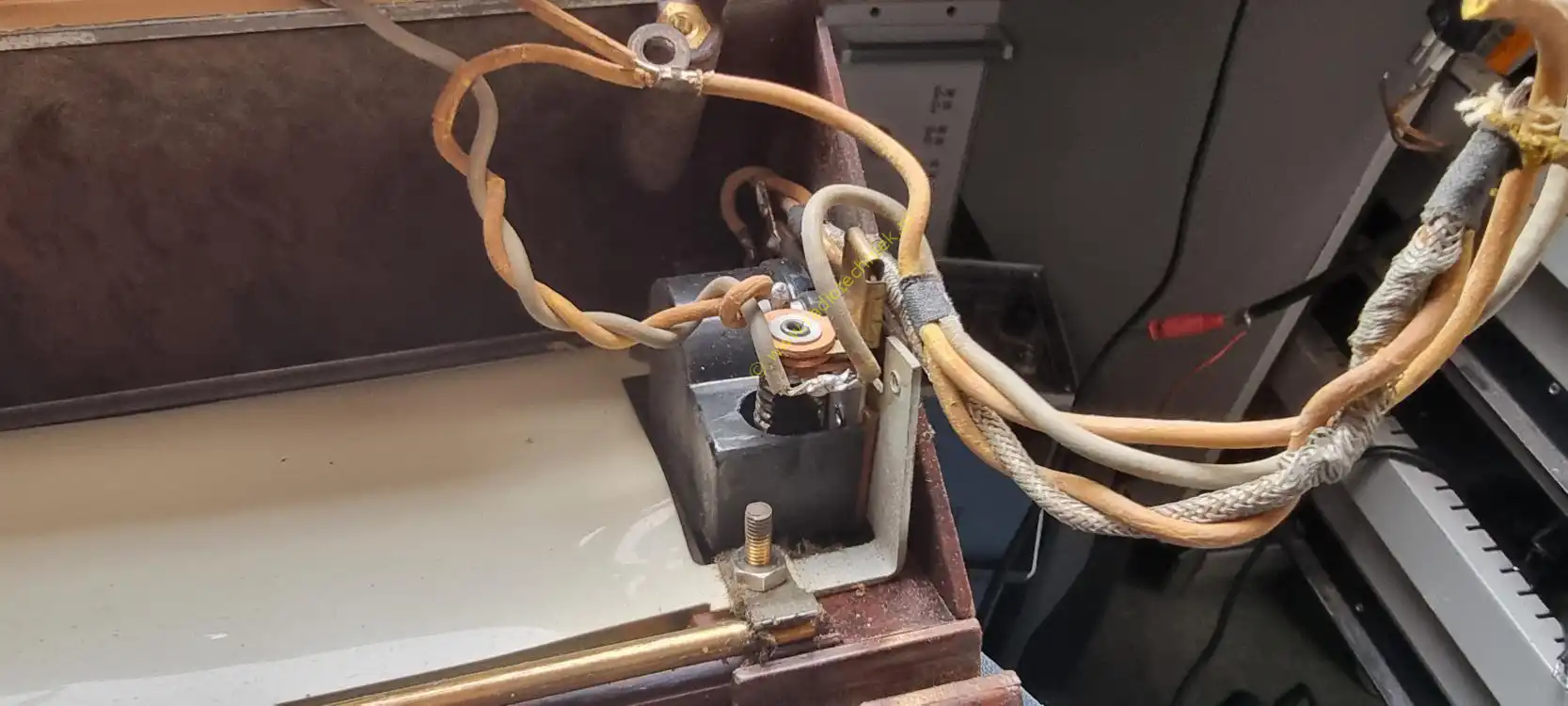
The mf band pass, there is clearly something wrong.
This radio has a variable bandwidth that is controlled in the first mf transformer. This is the complete stroke that the transformer can make.
This is after adjustment when the variable bandwidth is rotated from left to right.
And then fitting and measuring chassis wiring dial cover construction.
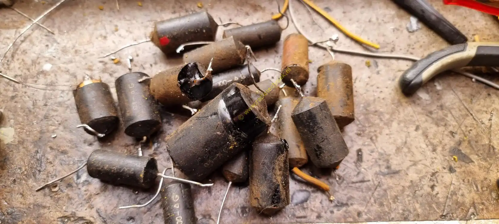
The leaking tar capacitors pile.
Placed the chassis back in the cabinet.
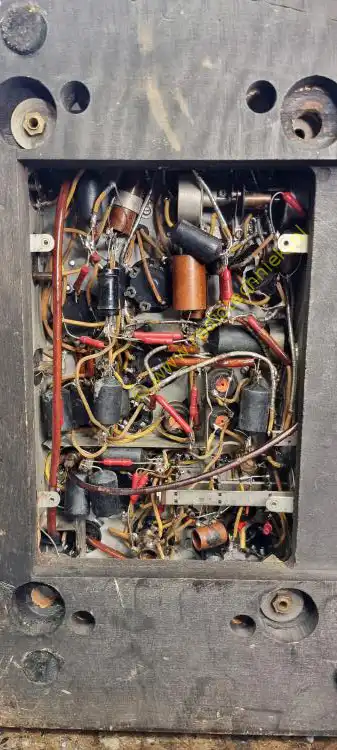
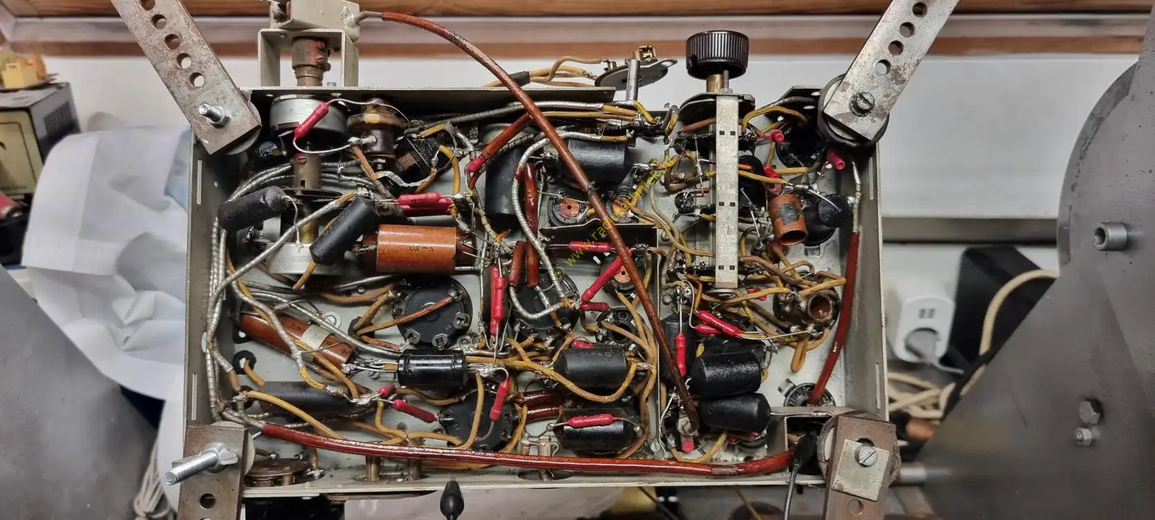
Could this radio have been restored on the bottom or is this just a fake?
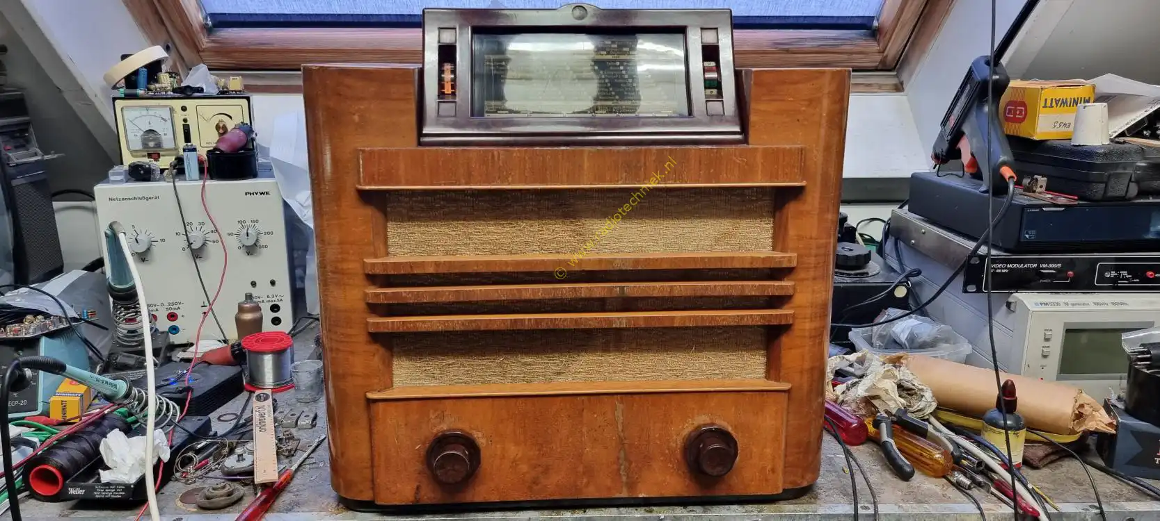
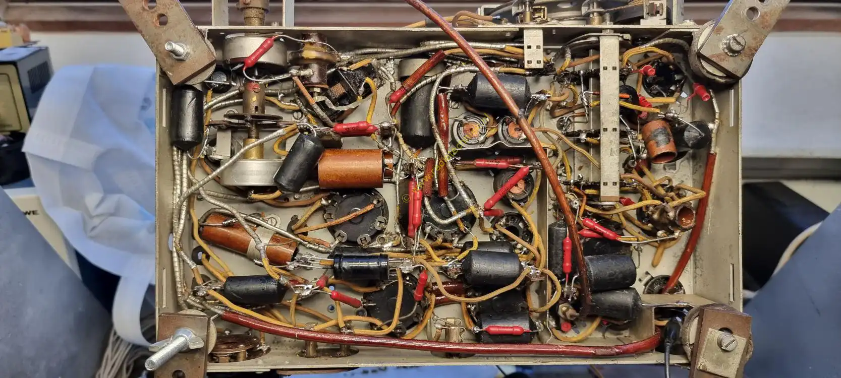
Playing the radio on the workbench.
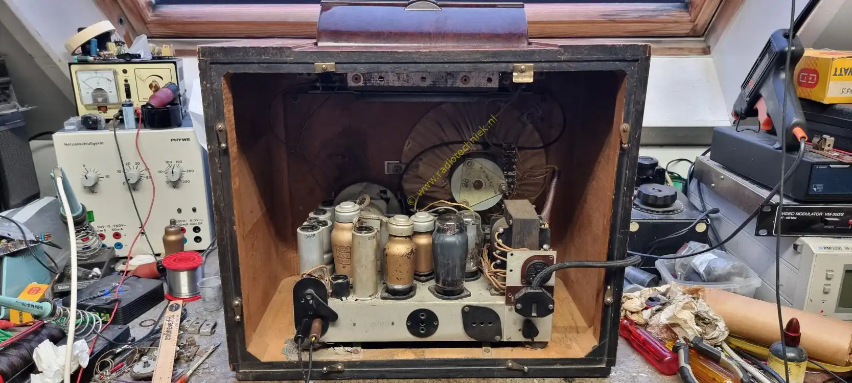
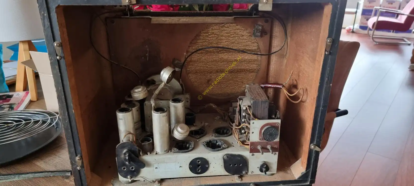
The inside of the radio.
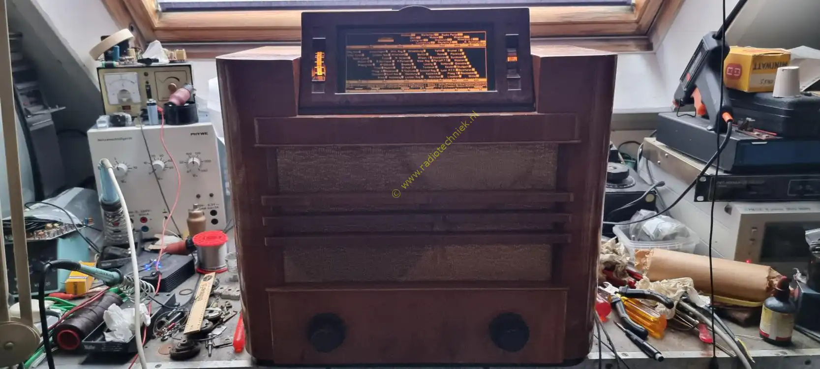
The dial lighting at this time I only had one diale lamp.
The radio has been completely restored, a device from 1936 built before the war. I hope I can keep this device alive. The people who worked on this device are probably no longer alive. But the memory in the form of this radio remains.
Listen to the radio and is an antenna needed?