Sometimes you ask yourself, can you also let a demolished KTV play?

If something no longer works, you can scrap such a device. And what would be the reason why it was demolished. Here I show that everything is fixable. It just doesn't matter how wrecked incomplete something is.

Look this is a line oscillator. You can use this to bend the image on a picture tube. And make high voltage to get light into the picture tube. And it just works.

Look this is part of a K80 chassis with a working line oscillator on it. The high voltage print is included separately. Fortunately, all the wires have been cut. So it's going to be a loose setup again.

And here the high voltage part and you guessed it the line transformer is defective.

Here's another test with a separate K8 transformer. And the high voltage works a bit. Then you immediately know why this television had to be demolished.

Because where could you find a line transformer? except nowhere.

They say. That they cannot be separated.

And yes I don't care about that I'm self wise people will say.

But you can unwind a line transformer very well.

What is immediately noticeable is that the insulation has completely decayed.

And look there. There you have a burn hole in the booster coil. Now you know right away that my ridiculous diagnosis is correct.

With some pieces of aluminum you can put some prints back together so that it is a whole.

I'm sorry I didn't get it right, but who cares.

The wiring is completely broken so we have to fix that.

Look there he is again. Nice it just keeps working.

Beautiful chassis, it is the Swedish version of the K8, but with much better PCBs and a completely different high voltage generator.

Here's a test with the vertical deflection also works. Incredible right?

Well enough played we need a power supply.

And because I didn't have a power supply print. I just made one myself. What else can you do.

Drill the holes first. And then mill some print traces with the dremel. It's nice that it's all possible.

You see it's becoming something.

Good enough it's time for a saw.

Just look beautiful. indistinguishable from the real thing.

See if we can solder some components on it.

So here we have a power supply for a Philips K80

The first test. The tubes burn beautifully. You just don't believe that.

And look how nicely that power supply fits behind the chassis.

And do you still recognize him. Now completely on its own power supply. You see the television is already workin a little bit.

There are a lot of transistor circuits on this chassis and they also need a power supply.

First the -25 volts.

Isn't it beautiful.

The plus 25 and the plus 12 also went like this and then...

Do you have noise and snow from the receiver.

OK then it's time to find a channel, maybe we can receive something on a demolition device.

Look wiring of the keypad made yes you can pull plugs. But cutting is more fun.

And look at the scope.

What do we recognize in this? Except nothing.

Yes of course video signal the TV receiver just works.

Look what a nice stable signal.

Spray the power supply board in the paint against oxide of the copper.

Isn't this nice setup? Front upside down. Then it stays.

Video from the PL802 can be transferred to a picture tube.

Well, beautiful puppet show, what are we missing now?

Precisely the line transformer that you will not find anywhere or should there be anyway.. no, don't believe it.

But with copper wire you can of course do some winding.

The first tests a booster voltage of 800 volts and still no fire.

That recoil impulse is beautiful, isn't it?

Look and this is how you do the first fire test. And you need that line oscillator for that.

OK more booster.

Just 1000 volts and continues to work who would have thought that.

And look at this line transformer, no horse will believe that.

The inner part is still original.

Coil for the cascade around it and go.

Look, pulses from the high voltage.

And look here, where is the line transformer.

Look where he belongs. There's the line transformer.

Focus print screwed onto the line transformer.

The booster is going well again.

Pulses are good for now.

And wow. The vertical deflection is also involved.

Video from the video amplifier.

Just the test image.

Rotten diode booster voltage seems OK.

No fire to be seen at all.

Pulses are beautiful.

High voltage tubes also love it.

And unloaded 27kv we are now missing one more thing. The picture tube.

All right, just hang a picture tube on the chassis.

And then there is also a picture. Who would have believed that.

A cabinet is not necessary. That's how it goes.

Beautiful image OK we are still missing something but that will come.

For now it works a bit.

And on the picture it looks beautiful.

Don't try this at home!!!

The BU126 on the side of the high voltage. Supplies part of the energy to the high voltage generator. And also the east / west is controlled via this circuit.

In my don't try this at home setup the bu126 continued to supply energy when only the low voltage power supply was still running. Normally this circuit is synchronized by the high voltage. Here it is now free running at a higher frequency than usual.

Because the wiring of the convergence panel was also cut. We had free run here.

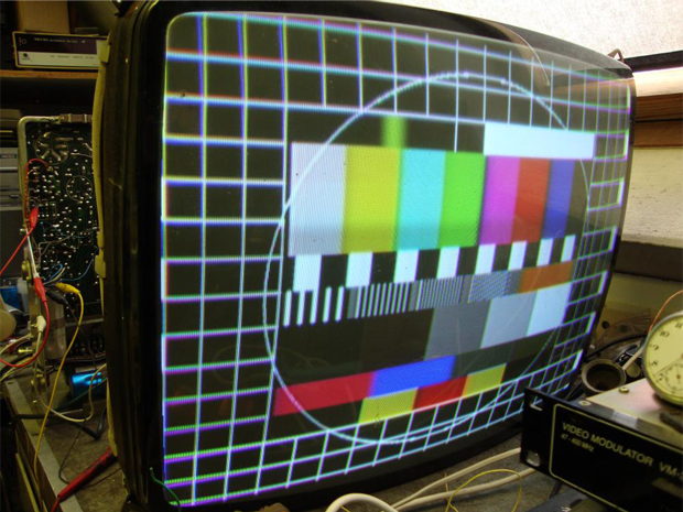
A setting and switching on and off of blue is also done via the convergence panel. That's why the image is a bit green.

With some tinkering with the pal identification we have color.

Pal identification.

The test image

color bars

Just the setup.

Fixed the wiring of the convergence panel.

Convergence and white balance adjusted.

Three good PCF200 tubes and then you do not know what you see.

The separate transformer provides the low voltage power supply. And I didn't have the right transformer. But with some help windings it went well.

Adjusting here and there.

Straighten east west.

Just the separate transformer, unfortunately I didn't have the original one. But it went fine.

And then the thing plays beautifully. So you see that everything can be repaired. But also know what you are doing. These kinds of experiments are life-threatening.