We are going to restore a demolished Philips L6x38T.

This print is green from oxide. Broken and loose print traces. But we're going to fix all this.

The chassis once fell and the bottom left is bent.

The chassis is otherwise in good condition.

After straightening the chassis we fit the front panel.

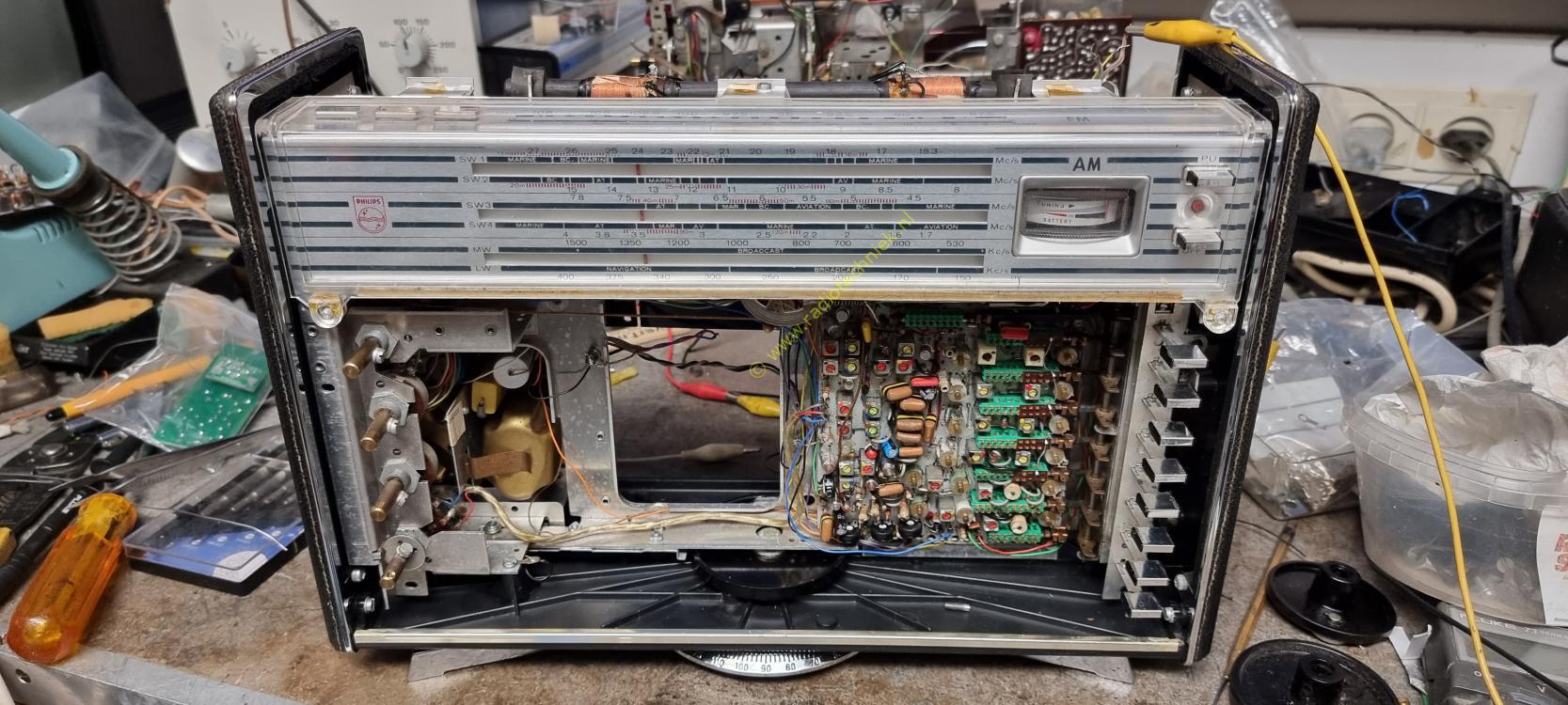
The rear gives a good idea of the chassis of this radio.

The top view of the chassis gives a nice idea of how this radio was built.

The side view.

And of course the push button mechanism is all aligned. The chassis is straight again and everything fits as intended.

The switches have now been removed from the PCB. The green corrosion is clearly visible. Some of the trimmers have also been removed for replacement.

Here the PCB is almost complete except for the potentiometers. The original Philips potentiometers are very old.

The power amplifier also needs some attention.

A leg of one of the transformers was broken.

Fixed the swivel foot lock.

And then the rebuild of the radio can begin.

First the AM tuning capacitor.

And of course the tuning string that you always have a huge argument with.

Dial in front and it looks like a real James Bond radio.

Amplifier board mounted with part of the wiring.

The pcb is now clean and partly restored

The top of the pcb looks neat again. This pcb is a pcb from 1965 that has not yet had any modifications.

Now also installed the potentiometers. Piher was chosen here because they are simply very good.

And this is what the pcb looks like after restoration.

And then the first test.....

Just listen along. The station is Extram, a local station is received without an antenna.

And now I'm playing for antenna, we still receive Extram on the medium wave.

Installing the wiring to the antenna gives the following result......

A wonderful AM radio time for FM.

Replacing a coil affected by corrosion along the way.

The location of the replaced coil is clearly visible on the print.

Clean the FM tuner board.

The closed FM tuner.

Put the stuff together and...

The construction of the chassis is of course not always easy. The print is very delicate and you have to pay close attention to what you are doing.

But all effort is rewarded. If you listen to the FM of this world receiver.

The mid frequency RF looks as it should.

The place from where it was measured.

Measurements at the FM detector.

Again the place of measurement.

Measurement of the transmittance curve of the RF Adjustment is clearly necessary.

The wiring is already starting to make good progress. After some test adjustment, another FM test....

While listening, my little friend came and sat next to me. Insanely sweet animal.

Switches are of course all broken. but luckily I found something.

Switches installed and wiring connected.

And wow the dial lighting works.

Meter and AM antenna mounted.

And of course the connection panel is also a hassle, but it all works out in the end.

And then the chassis is quite complete.

My little friend.

Time for adjustment.

FM Detector transmission curve in slow motion.

Just the image of the FM detector.

We've come a long way. Unfortunately I am still looking for the 1965 scale for this radio.

And just listen for a moment...